Digilent 410-215P Bedienungsanleitung

Stöbern Sie online oder laden Sie Bedienungsanleitung nach Hardware Digilent 410-215P herunter. Digilent 410-215P User Manual [en] [de] [it] Benutzerhandbuch

  • Herunterladen
  • Zu meinen Handbüchern hinzufügen
  • Drucken
  • Seite
    / 2
  • Inhaltsverzeichnis
  • LESEZEICHEN
  • Bewertet. / 5. Basierend auf Kundenbewertungen
Seitenansicht 0
P
P
m
m
o
o
d
d
G
G
Y
Y
R
R
O
O
R
R
e
e
f
f
e
e
r
r
e
e
n
n
c
c
e
e
M
M
a
a
n
n
u
u
a
a
l
l
Revision: August 3, 2011
Note: This document applies to Rev. A of the board.
1300 NE Henley Court, Suite 3
Pullman, WA 99163
(509) 334 6306 Voice | (509) 334 6300 Fax
Doc: 502-215 page 1 of 2
Copyright Digilent, Inc. All rights reserved. Other product and company names mentioned may be trademarks of their respective owners.
Overview
The PmodGYRO is a peripheral module
featuring the STMicroelectronics® L3G4200D
MEMS motion sensor. The L3G4200D
provides a three-axis digital output gyroscope
with built in temperature sensor.
Features include:
Standard SPI and I
2
C™ interface
250/500/2000dps Selectable
Resolutions
Two customizable interrupt pins
Power-down and Sleep Mode
User configurable signal filtering
Functional Description
The PmodGYRO uses a standard 12-pin
connection and communicates via SPI or I
2
C,
defaulting to I
2
C communication. A pull-up
resistor on the CS line keeps the device in I
2
C
mode unless the CS line is driven low by the
master device
Interface
When communicating with the device the
master must provide a register address and a
flag specifying whether the subsequent action
is a read or write. The actual transfer of data
follows this command. Through this method,
the user can either configure the device by
writing to specific control registers within the
device, or read back data from separate read-
only registers.
Two interrupts directly map to pins available to
the user on connector J1 of the PmodGYRO.
The configuration of INT1, present on pin 7 of
J1, is entirely user customizable. The main use
of INT1 stems from high and low events on the
three axes about which the gyroscope
measures angular speed. By default, the INT1
is disabled. The second interrupt, INT2, is
primarily used for data ready and FIFO
interrupts and maps to pin 8 on J1.
For more information about the control
registers, data collection, and interrupt settings
available for user configuration, see the data
sheet for the L3G4200D on the
STMicroelectronics® website.
SPI Communication
The SPI interface uses three or four signal
lines for communication depending on the
current configuration of the device. These are
Chip Select (CS), Serial Data In (SDI) or
simply Serial Data (SDA) in 3-wire SPI mode,
Serial Data Out (SDO), and Serial Clock
(SCL). The PmodGYRO defaults to the 4-wire
operating mode. In order to use the 3-wire
mode, a control register must be written to. For
more detailed SPI communication, refer to the
device data sheet.
Seitenansicht 0
1 2

Inhaltsverzeichnis

Seite 1 - Functional Description

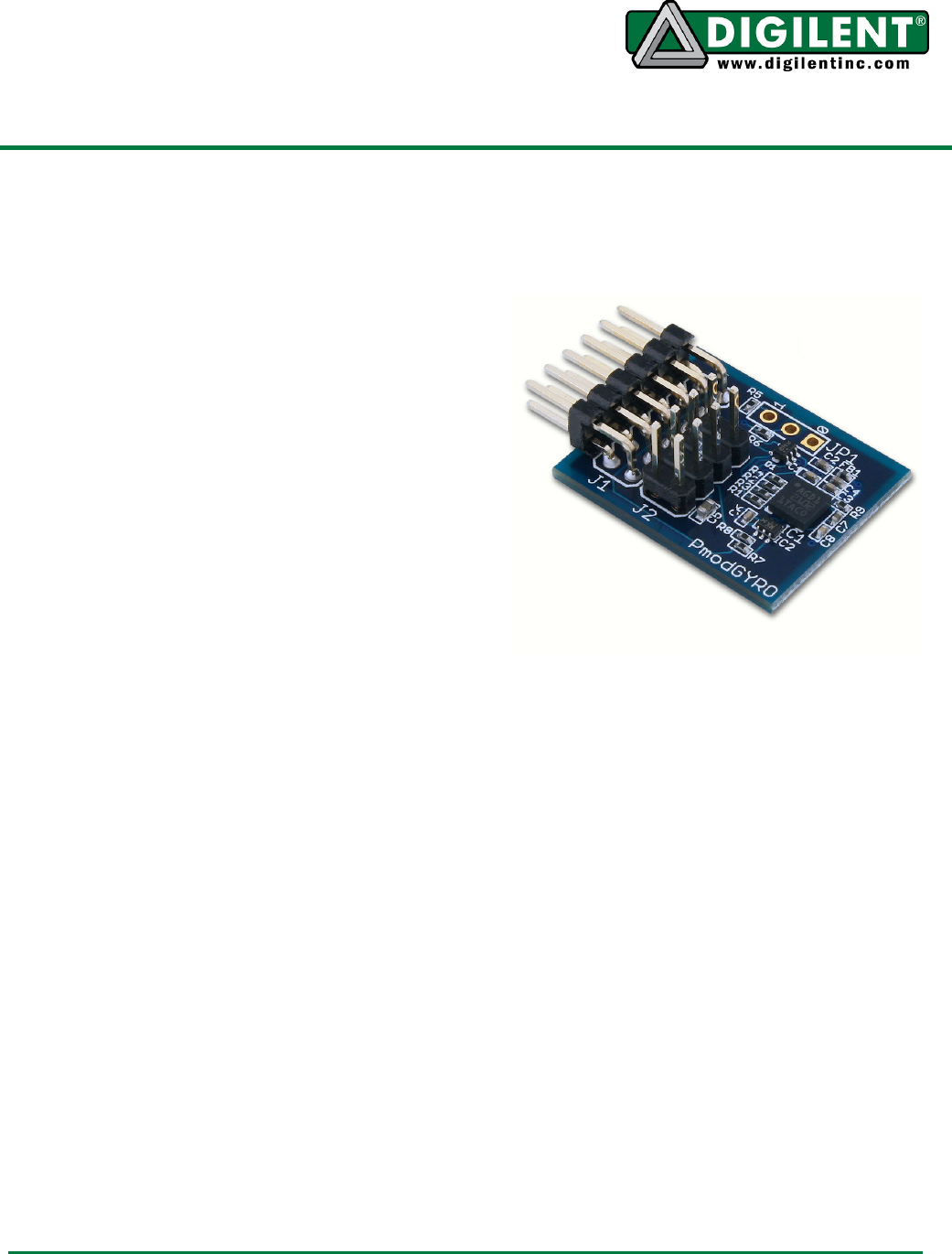
PPmmooddGGYYRROO™™ RReeffeerreennccee MMaannuuaall Revision: August 3, 2011 Note: This document applies to Rev. A of the board. 1300 NE Henley Cour

Seite 2 - PmodGYRO™ Reference Manual

PmodGYRO™ Reference Manual ® www.digilentinc.com www.digilentinc.com Copyright Digilent, Inc. page 2 of 2 I2C Communication The I2C standa

Kommentare zu diesen Handbüchern

Keine Kommentare